|
The Southern Speargun
Handle and butt
The rear end of the gun is the butt. Just in front of the butt, is the handle. The handle contains the spear release mechanism (Picasso shot engine). The handle is jointed securely to the rear end of the stock.
The handle and butt consist of several pieces of wood, fitting together like pieces of a puzzle. To make the arrangement easier to explain, it helps to divide them into the middle pieces and the side plates.
Middle pieces
The middle pieces are in the centre, between the outer side plates. They sit to the rear of, and follow-on from, the middle laminate of the stock.
Shot engine
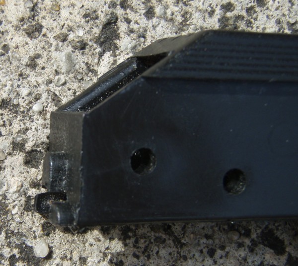
When the completed gun was loaded, the spear was held in place by the shot engine (till the trigger was pulled). The shot engine sat directly behind the middle piece of the stock. It wasn’t glued to any of the wooden pieces, but sat in a pocket surrounded by the side pieces and with the handle proper at the rear. It was held in the pocket by stainless steel screws, screwed in through the side pieces and into holes in the body of the shot engine.
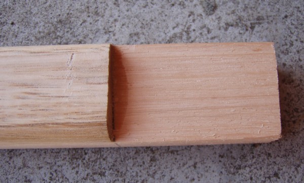
The stock had been previously glued. The “D”-shaped cross section side pieces did not extend all the way to its rear end, leaving a middle tongue of wood protruding. The tongue was 50 mm long, and was just marginally wider than the shot engine.
The front of the shot engine abutted onto the rear of the tongue. The shot engine has three short lugs protruding from the lower part of the front. I had to cut wood away from the bottom of the rear face of the tongue to make room for the lugs. Using a saw, I cut out a rectangle; 4 millimetres from the back face of the tenon and 25 millimetres up from the bottom. This left a lip on the top of the rear face of the tongue, which was 5 millimetres thick. The lugs fit into the recess below the lip.
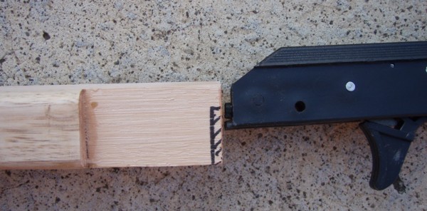
To check that the dimensions were correct, I dry-fitted the shot engine by placing its front next to the rear of the stock. The lugs fitted up under the lip, and the edge of the taper on the front of the mechanism was flush with the top of the tenon.
Trigger-guard middle-piece
I had to fit together the various pieces of wood that make the handle and trigger guard.
The pocket for the shot engine is hollow (until the shot engine is placed in it of course). This has the potential to weaken the handle. The side plates outside the pocket boost the strength, as does the trigger guard below the shot engine.
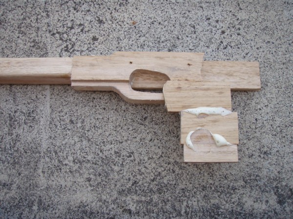
The wooden trigger guard sits below the line of the bottom of the stock. To make it, I had to glue a strip of wood under the tongue. This piece was made from a 200 mm long strip taken from the same piece of lumber used for the stock centre laminate.
The top of the trigger guard piece supported the bottom of the front of the shot engine, that is, it had to sit higher than the line of the bottom of the stock. To make it fit, I cut away a rectangular section 50 millimetres long (to come to the rear end of the “D”-shaped outer laminates) and 12 millimetres deep.
After cutting, I dry-fitted the trigger guard piece under the tongue to see how it fit. The front of the piece came flush with the rear of the “D”-shaped side laminates.
I glued the trigger-guard middle-piece to the bottom of the tongue, taking care that the sides of the tongue were flush and parallel with the trigger guard piece,.
When the glue had cured, I removed drips and smoothed it all.
I tried dry-fitting the shot engine. There was room for the lugs, and the bottom of the engine did not foul on the top of the trigger-guard middle-piece. However, the actual trigger did foul on the middle-piece and I needed to cut a trigger and finger hole. To work out where the hole should be, I took a pencil and drew around the position of the trigger. I did this when the trigger was at rest, and when it was pulled back fully. Using these as a guide, I sketched on the proportions of the trigger hole
Looking at what I sketched, it seemed to me that once I had cut out the trigger hole, the remaining wood would be a little thin along the bottom, and really needed to be bulked-up. I sawed a thin strip from the square edge 40 x 18 millimetres and glued it along the bottom of the trigger guard piece.
When the glue had cured, I removed unwanted wood with a saw, then flattened it with sand paper.
Following the lines I had drawn, I used a coping saw to remove unwanted wood and create the empty space which would fit the trigger and my trigger finger. I made the cuts a little short of what might be ideal, working on the basis that if I made a mistake, it was easy to rasp or cut away more later.
The rear of the trigger guard middle piece was trimmed to make another tongue, which would later be fitted into the handle middle piece.
Handle middle piece
I needed to joint the tongue at the rear of the trigger guard piece to the middle piece for the handle (the rear of which would also be at the butt).
The handle piece needed to be wider than any of the wood I had purchased. I took two 150 mm long pieces of 30 mm x 18mm strips and glued them together along their narrow edges. After gluing, I had a piece 150 mm x 60 mm x 18 mm. This piece was to be shaped into the handle middle plate.
Wood is stronger along the grain than it is across the grain. To maximise strength, I ran the grain along the long axis of the handle, angled back to match the line of the handle.
There was a tongue extending from the rear of the trigger guard piece. I sawed an angled slot into the handle to joint it to this tongue. I glued the tongue into the slot in the handle. To keep it all true and flat, I clamped on a flat piece (this was not glued, and was removed later). Once the glue was dry, I removed the clamps and cleaned up the joint.
I laid the shot engine on middle pieces and drew a pencil line around it. I cut out the rear profile of the shot engine hole with a coping saw. Sawing was a little tricky as the trigger guard is thin, and could break if too much force is applied. But a bit of care and careful clamping in the vice got the job done without disaster.
The centre pieces were now together.
Side plates and shot engine
In the completed gun, there were side plates on either side of the shot engine.
Side plates
The middle pieces are narrow (18 mm). To bulk out the handle, and provide strength along the sides of the shot engine pocket, I added plates of 8 mm x 42 mm DAR (dressed all round) mouldings.
I glued on the side plates, one side of the gun at a time. Doing it this way allowed me to fit the shot engine locating screws with greater accuracy. The distance of from the top of the handle/butt to the bottom of the handle is greater than 42 mm, so a series of plates are laid and glued on to the middle plates. I found it easier to glue-on one plate, let the glue set, clean it up and then glue on another – and so on, rather than try to do it all at one time. It was slower that way, but the final result was neater.
The first side plate I glued was the top one. In the completed gun, the mechanism sits above the top of the handle, 5 millimetres higher than level of the stock, so the side plate has to be lifted appropriately, and the parts forward of the shot engine later trimmed down to the level of the stock.
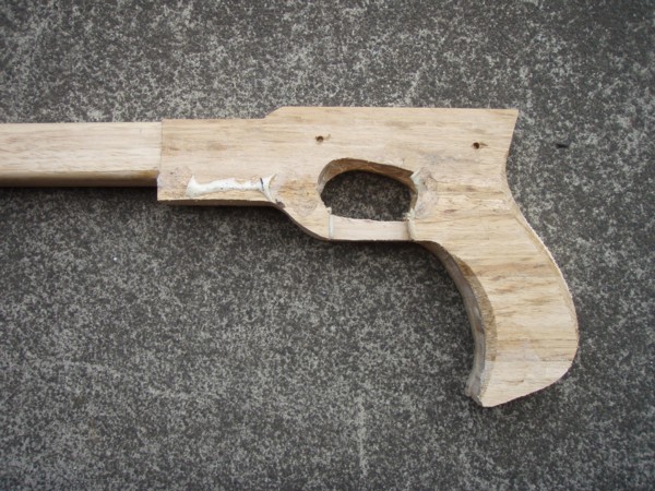
Once s side plate was glued on, the handle was much stronger. I took the opportunity to cut out the shape of the handle and clean up the profile a little. I also cut the back of the handle and butt (don’t make the wood behind the shot engine too thin as this is a weak part of the design). The diagram included with the pictures gives an idea of how this was done. At the front of the trigger guard, I cut it so that there would be a continuous line once the shooting line clip was installed.
It was starting to look like a speargun handle!
Fitting mech and screws
I dry-fitted the shot engine, and used it as a template to drill 3.5 mm holes for the securing screws.
I glued-on the other side plate, let the glue set, re-inserted the mech, and drilled through from side that already had holes. I did this gently to minimise any removal of plastic in the mech.
In the completed gun, after varnishing, I used stainless steel screws to hold the shot engine in place. The outsides of the threads were slightly larger than the 3.5 mm holes in the handle and the holes in the plastic body of the shot engine.
I cut out the upper parts of the trigger finger hole using the coping saw. As this was the initial rough cut, which would most likely need to be fine tuned later, I left a little spare wood for later removal.
Building-up the handle
I glued the series of 8 mm x 42 strips down each side of the handle middle plate. These were done one at a time, waiting for the glue to set, cleaning out the waste, then gluing on he the next plate. There were overhanging bits of side plate sticking out. I cut the waste off with a coping saw, and neatened it with the wood rasp.
Then I did the other side. I also did a bit of preliminary cleaning up inside the trigger hole.
Shaping
The first lot of shaping was in the square, but I then rounded the edges with the rasp and improved the finish with 80 grit sand paper. The grain came up a treat, with a brindle look (like a brown camo suit).
It occurred to me that the rough texture left by the rasp could have been an anti-slip surface on the handle, but the brindle grain looked so good I thought I would do it smooth and shiny.
The tricky bits were on the edges of the trigger guard. Persistence brought success.
When the handle sat in my hand, it was a little longer than needed, so I trimmed about ten millimetres from the bottom. I also let my hand tell me if there were any parts of the handle that were uncomfortable. I rasped these pieces away.
(one picture was too big to upload - with luck I will edit it in later)
| Attachments: |
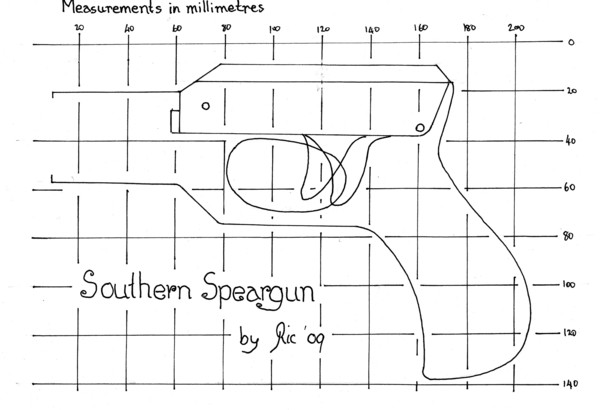
01. handle diagram.jpg [ 41.89 KiB | Viewed 11382 times ]
|
03. side view of tongue on stock.JPG [ 62.75 KiB | Viewed 11382 times ]
|
04. front face shot engine with lugs.JPG [ 94.3 KiB | Viewed 11382 times ]
|
05. calculating lip depth.JPG [ 61.39 KiB | Viewed 11382 times ]
|
06. checking cut away.JPG [ 68.14 KiB | Viewed 11382 times ]
|
07. trigger guard under-piece glued on.JPG [ 82.42 KiB | Viewed 11382 times ]
|
08. cutting mech recess.JPG [ 79.7 KiB | Viewed 11382 times ]
|
09.trig guard end trimmed down to tenon.JPG [ 68.26 KiB | Viewed 11382 times ]
|
10. glueing handle piece to trigger guard tongue.JPG [ 71.27 KiB | Viewed 11382 times ]
|
11. cut-out handle piece with side plate.JPG [ 104.63 KiB | Viewed 11382 times ]
|
12. drilling mech holes.JPG [ 90.47 KiB | Viewed 11382 times ]
|
13. building up handle.JPG [ 103.13 KiB | Viewed 11382 times ]
|
14. building up handle 1.JPG [ 112.84 KiB | Viewed 11382 times ]
|
15. handle in the square.JPG [ 107.57 KiB | Viewed 11382 times ]
|
_________________
Ric Fallu started spearfishing in Pt Phillip in the early 1960s, and never really stopped
|